Plane in space - necessary information. Ways to define a plane Three ways to define a plane
The plane is one of the most important figures in planimetry, so you need to have a good understanding of what it is. Within the framework of this material, we will formulate the very concept of a plane, show how it is denoted in writing, and introduce the necessary notations. Then we will consider this concept in comparison with a point, line or other plane and analyze the options for their relative position. All definitions will be illustrated graphically, and the necessary axioms will be formulated separately. In the last paragraph we will indicate how to correctly define a plane in space in several ways.
Yandex.RTB R-A-339285-1
A plane is one of the simplest figures in geometry, along with a straight line and a point. We have already explained earlier that a point and a line are placed on a plane. If we place this plane in three-dimensional space, then we will get points and lines in space.
In life, an idea of what a plane is can be given to us by objects such as the surface of a floor, table or wall. But we must take into account that in life their sizes are limited, but here the concept of plane is associated with infinity.
We will denote straight lines and points located in space similarly to those located on a plane - using lowercase and uppercase Latin letters (B, A, d, q, etc.) If, in the conditions of the problem, we have two points that are located on a straight line, then you can choose designations that will correspond to each other, for example, straight line D B and points D and B.
To represent a plane in writing, small Greek letters such as α, γ, or π are traditionally used.
If we need a graphical representation of a plane, then usually a closed space of arbitrary shape or a parallelogram is used for this.
The plane is usually considered together with straight lines, points, and other planes. Problems with this concept usually contain some variants of their location relative to each other. Let's consider individual cases.
The first way of relative position is that the point is located on a plane, i.e. belongs to her. We can formulate an axiom:
Definition 1
There are points in any plane.
This arrangement is also called passing the plane through a point. To indicate this in writing, the symbol ∈ is used. So, if we need to write down in letter form that a certain plane π passes through a point A, then we write: A ∈ π.
If a certain plane is given in space, then the number of points belonging to it is infinite. What minimum number of points will be enough to define a plane? The answer to this question is the following axiom.
Definition 2
A single plane passes through three points that are not located on the same straight line.
Knowing this rule, you can introduce a new designation for the plane. Instead of a small Greek letter, we can use the names of the points lying in it, for example, plane A B C.
Another way of the relative position of a point and a plane can be expressed using the third axiom:
Definition 3
You can select at least 4 points that will not be in the same plane.
We have already noted above that to designate a plane in space, three points will be enough, and the fourth can be located both in it and outside it. If you need to indicate that a point does not belong to a given plane in writing, then the sign ∉ is used. A notation of the form A ∉ π is correctly read as “point A does not belong to the plane π”
Graphically, the last axiom can be represented as follows:

The simplest option is that the straight line is in the plane. Then there will be at least two points of this line located in it. Let us formulate the axiom:
Definition 4
If at least two points of a given line are in a certain plane, this means that all points of this line are located in this plane.
To write down the belonging of a straight line to a certain plane, we use the same symbol as for a point. If we write “a ∈ π”, then this will mean that we have a straight line a, which is located in the π plane. Let's depict this in the figure:

The second variant of the relative position is when the straight line intersects the plane. In this case, they will have only one common point - the point of intersection. To write this arrangement in letter form, we use the symbol ∩. For example, the expression a ∩ π = M reads as “the line a intersects the plane π at some point M.” If we have an intersection point, then we also have the angle at which the straight line intersects the plane.
Graphically, this arrangement looks like this:

If we have two straight lines, one of which lies in a plane and the other intersects it, then they are perpendicular to each other. In writing this is indicated by the symbol ⊥. We will consider the features of this position in a separate article. In the figure, this arrangement will look like this:

If we are solving a problem that involves a plane, we need to know what the normal vector of the plane is.
Definition 5
The normal vector of a plane is a vector that lies on a line perpendicular to the plane and is not equal to zero.
Examples of normal plane vectors are shown in the figure:

The third case of the relative position of a straight line and a plane is their parallelism. In this case, they do not have a single common point. To indicate such relationships in writing, the symbol ∥ is used. If we have a notation of the form a ∥ π, then it should be read as follows: “the line a is parallel to the plane ∥”. We will analyze this case in more detail in the article about parallel planes and straight lines.

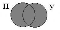
If a straight line is located inside a plane, then it divides it into two equal or unequal parts (half-plane). Then such a straight line will be called the boundary of the half-planes.
Any 2 points located in the same half-plane lie on the same side of the boundary, and two points belonging to different half-planes lie on opposite sides of the boundary.
1. The simplest option is that two planes coincide with each other. Then they will have at least three common points.
2. One plane can intersect another. This creates a straight line. Let us derive the axiom:
Definition 6
If two planes intersect, then a common straight line is formed between them, on which all possible points of intersection lie.
On the graph it will look like this:

In this case, an angle is formed between the planes. If it is equal to 90 degrees, then the planes will be perpendicular to each other.
3. Two planes can be parallel to each other, that is, not have a single intersection point.

If we have not two, but three or more intersecting planes, then such a combination is usually called a bundle or a bunch of planes. We will write more about this in a separate article.
In this paragraph we will look at what methods exist for defining a plane in space.
1. The first method is based on one of the axioms: a single plane passes through 3 points that do not lie on the same line. Therefore, we can define a plane simply by specifying three such points.
If we have a rectangular coordinate system in three-dimensional space in which a plane is specified using this method, then we can create an equation for this plane (for more details, see the corresponding article). Let's illustrate this method in the figure:

2. The second method is to define a plane using a line and a point not lying on this line. This follows from the axiom about a plane passing through 3 points. See picture:

3. The third method is to specify a plane that passes through two intersecting lines (as we remember, in this case there is also only one plane.) Let us illustrate the method like this:

4. The fourth method is based on parallel lines. Let us remember which lines are called parallel: they must lie in the same plane and not have a single point of intersection. It turns out that if we indicate two such lines in space, then we will thereby be able to define for them that very single plane. If we have a rectangular coordinate system in space in which a plane has already been defined in this way, then we can derive the equation of such a plane.
In the figure, this method will look like this:

If we remember what a parallelism sign is, we can derive another way to define a plane:
Definition 7
If we have two intersecting lines that lie in a certain plane, which are parallel to two lines in another plane, then these planes themselves will be parallel.
Thus, if we specify a point, we can specify the plane that passes through it and the plane to which it will be parallel. In this case, we can also derive the equation of the plane (we have a separate material on this).

Let us recall one theorem studied in a geometry course:
Definition 8
Only one plane can pass through a certain point in space, which will be parallel to a given straight line.
This means that you can define a plane by specifying a specific point through which it will pass and a line that will be perpendicular to it. If a plane is defined in this way in a rectangular coordinate system, then we can write an equation of the plane for it.

We can also specify not a straight line, but a normal vector of the plane. Then it will be possible to formulate a general equation.

We looked at the main ways in which you can define a plane in space.
If you notice an error in the text, please highlight it and press Ctrl+Enter
The position of a plane in space is determined by its three points that do not lie on the same straight line. Therefore, to define a plane on a diagram, it is enough to specify three of its points (Fig. 206). The plane can be defined by a point and a straight line (Fig. 207, a), two parallel straight lines (Fig. 207, b), two intersecting straight lines (Fig. 207, c), a triangle (Fig. 207, d).

You can define a plane with traces. The trace of a plane is the straight line along which this plane intersects the projection plane. In Fig. 208 Pv - frontal trace of plane P, Рн - horizontal trace of plane P, Pw - profile trace of plane P.

Various cases of arrangement of planes relative to projection planes
General plane - a plane located obliquely to all projection planes (Fig. 208). Such a plane intersects with three projection planes along straight lines, which are traces of this plane. Each pair of traces converges at a point called the vanishing point of the plane traces and is located on the projection axis. A general position plane has three vanishing points, which are designated Px, Py, Pz. At these points the plane intersects the coordinate axes. Plane figures lying in a general plane are projected with distortion.
Projection plane - a plane perpendicular to any projection plane.
Horizontal projection plane - plane perpendicular to the horizontal plane of projections H (Fig. 209).

Frontal projection plane - plane perpendicular to the frontal plane of projection (Fig. 210).

Profile-projecting plane - plane perpendicular to the profile plane of projections (Fig. 211).

The projecting plane is projected onto the projection plane to which it is perpendicular to a straight line. Pa Fig. 209 plane P is horizontally projecting, ΔАВС, lying in the plane P, is projected into a straight line segment that coincides with the trace of the plane Рн. In Fig. 210 ΔDEF, belonging to the frontally projecting plane R, is projected into a segment coinciding with the trace of the plane Rv. In Fig. 211 ΔKMN, lying in the profile-projecting plane Q, is projected onto the W plane into a segment coinciding with the trace of the Qw plane. Therefore, projection planes are often used as auxiliary planes in various constructions. For example, in order to draw a horizontally projecting plane through straight AB (Fig. 212), it is enough to draw a horizontal trace of this plane through the horizontal projection of straight AB, since everything that lies in this plane, including straight AB, is projected onto its horizontal track. The frontal trace of the frontally projecting plane coincides with the frontal projection of straight line a"b" (Fig. 213). The traces of the projecting planes on other projection planes are perpendicular to the corresponding projection axes (see Fig. 209, 210, 211).

Rice. 212 Fig. 213
Planes perpendicular to two projection planes are parallel to the third projection plane . Geometric figures lying in these planes are projected without distortion onto the projection plane to which this plane is parallel (Fig. 214, 215; 216). Such planes are called the same as the projection plane parallel to which they are located: horizontal plane (Fig. 214), frontal plane (Fig. 215), profile plane (Fig. 216).
Now we will list the main ways to define a specific plane in space.
Firstly, a plane can be defined by fixing three points in space that do not lie on the same straight line. This method is based on the axiom: through any three points that do not lie on the same line, there is a single plane.
If a rectangular coordinate system is fixed in three-dimensional space and a plane is specified by specifying the coordinates of its three different points that do not lie on the same straight line, then we can write the equation of the plane passing through the three given points.
The next two methods of defining a plane are a consequence of the previous one. They are based on corollaries of the axiom about a plane passing through three points:
· a plane passes through a line and a point not lying on it, and only one (see also the article equation of a plane passing through a line and a point);
· a single plane passes through two intersecting lines (we recommend that you familiarize yourself with the material in the article: equation of a plane passing through two intersecting lines).


The fourth method of defining a plane in space is based on defining parallel lines. Recall that two lines in space are called parallel if they lie in the same plane and do not intersect. Thus, by indicating two parallel lines in space, we will determine the only plane in which these lines lie.
If in three-dimensional space relative to a rectangular coordinate system a plane is specified in the indicated way, then we can create an equation for a plane passing through two parallel lines.

The sign of parallelism of two planes gives us another way to define a plane. Let us recall the formulation of this feature: if two intersecting lines of one plane are respectively parallel to two lines of another plane, then such planes are parallel. Therefore, we can specify a specific plane if we specify the point through which it passes and the plane to which it is parallel.
In high school geometry lessons, the following theorem is proven: through a fixed point in space there passes a single plane perpendicular to a given line. Thus, we can define a plane if we specify the point through which it passes and a line perpendicular to it.
If a rectangular coordinate system is fixed in three-dimensional space and a plane is specified in the indicated way, then it is possible to construct an equation for a plane passing through a given point perpendicular to a given straight line.
Instead of a line perpendicular to the plane, you can specify one of the normal vectors of this plane. In this case, it is possible to write a general equation of the plane.
You can also find the information you are interested in in the scientific search engine Otvety.Online. Use the search form:
More on the topic Methods for defining a plane:
- 13. Thinking disorders: by tempo, structure, purposefulness. Diagnostic value of symptoms.
- Main directions in the study of thinking disorders in schizophrenia.
- Classification of thinking disorders in the works of B.V. Zeigarnik.
- 8. Analysis of the specifics of methods of special psychology in comparison with methods of other branches of psychology: the use of standardized techniques (tests), the use of questionnaires, the method of analyzing activity products.
- 14. Methods for studying the area of geometric figures and developing skills in measuring it. Familiarization with units of area measurement and their relationships. Peculiarities of perception of a junior schoolchild. Taking into account the laws and principles of education when studying the area of geometric shapes.
Methods for specifying a plane that uniquely determine the position of the plane in space (see Fig. 16):
a) three points that do not lie on the same line;
b) a line and a point outside the line;
c) parallel lines;
d) intersecting lines.
e) flat figure;
On the diagram, the plane is defined by the projections of the listed geometric elements and traces. These elements are called the plane determinant (∆).
The plane in space can be specified by traces (see Fig. 17). The trace of a plane is the line of intersection of a given plane with the projection plane. In a system of three projection planes, the plane of general position p(not perpendicular and not parallel to the projection planes) can have three traces - horizontal ( R 1 ), front ( R 2 ), profile ( R 3 ); Рх, Ру, Рz- vanishing points of tracks (Fig. 17)

3.2. Planes of particular position.
The planes of particular position include:
Projection planes, i.e. planes perpendicular to one of the projection planes (Fig. 18);
Level planes are planes parallel to one of the projection planes (Fig. 19).
3.3. Projection planes
Features of projection planes:
1. One projection of any element located in the projecting plane coincides with the corresponding trace of this plane;
2. On the diagram, the angle of inclination of a given plane to the projection plane is projected into the true value (Fig. 18).

3.4. Level planes
A feature of level planes is that any flat figure located in such a plane is projected onto a plane parallel to it without distortion, i.e. to the true value (Fig. 19).

To construct elements located in a general plane, you need to follow two rules:
A straight line belongs to a plane if it passes through two points lying in the plane or if it passes through a point lying in the plane and parallel to another straight line located in this plane (Fig. 20);
A point lies in a plane if it lies on a straight line located in this plane (Fig. 21).

3.6. Main lines of the plane.
Horizontal (h) - a straight line lying in a plane and at the same time located parallel to the plane P 1 (Figure 22). Frontal ( f) - a straight line lying in the plane and parallel to the plane P 2 . The line of greatest inclination is a straight line lying in a plane and perpendicular to either the horizontals or fronts of the plane. Using the line of greatest inclination, the angle of inclination of the plane to the projection planes is determined. The line of greatest inclination located perpendicular to the horizontals of the plane is also called the slope line of the plane (VC Fig. 22).

Using the slope line, the angle of inclination of the plane is determined ABC to the horizontal projection plane. To do this, it is necessary to determine its natural size using the method of a right triangle and the angle between the natural size and the horizontal projection will be the desired angle.
3.7. Self-test questions.
List and depict graphical methods for defining a plane in a complex drawing.
What is meant by the trace of a plane?
What plane is called the projecting plane and what are its graphical features in the drawing?
Give graphic characteristics to the planes: horizontally - projecting, frontally - projecting, profile - projecting.
Which plane is called the level plane?
What plane is called horizontal? Frontal?
Profile? Draw them on the drawing.
Name the signs of belonging to a straight plane, points of the plane.
Show in the drawing how a straight line can be enclosed in a plane.
Name the main lines of the plane.
How to determine the angle of inclination of a plane to the horizontal plane of projections?
Any geometric figure immersed in space consists of a certain set of points in space. A plane, as one of the geometric figures, is a collection of many points. From this definition of a plane, it is possible to establish ways to define its position in space. To do this, it is enough to remember the combination axiom - through three points that do not lie on the same line, you can draw a plane, and only one.
In Fig. 21 shows ways to set the position of the plane in space:
a – three points that do not lie on the same line;
b – a straight line and a point taken outside the straight line;
c – two intersecting straight lines;
d – two parallel straight lines.
In a complex drawing (Fig. 22), the plane can be specified:
a – projections of three points that do not lie on the same line;
b – projections of a line and a point taken outside the line;
c – projections of two intersecting lines;
Each of those shown in Fig. 22 ways to define a plane in a drawing can be converted from one to another. So, for example, by drawing a straight line through points A and B (Fig. 22, a), we obtain the plane assignment shown in Fig. 22, b. From this you can move on to the method presented in Fig. 22, d, if through point C we draw a line parallel to line AB. If points A, B and C are connected in pairs by straight lines, then we get triangle ABC - a flat figure (Fig. 23), the projections of which can define a plane in the drawing.

 It should always be remembered that the plane, as a geometric figure, is limitless and therefore cannot be limited to constructions only within the area of this triangle, since in the general case the projections of the plane occupy the entirety of each of the projection planes: horizontal P I, frontal P 2 and profile P 3.
More clearly, the plane can be defined using straight lines along which it intersects the projection planes (Fig. 24, a).
These lines are called traces of the plane. In general, both tracks must intersect each other at a point on the projection axis, which is called the “vanishing point of the tracks.”
 From the whole variety of positions of the plane relative to a given system of projection planes, those are usually distinguished when.